|
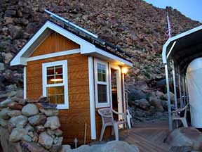
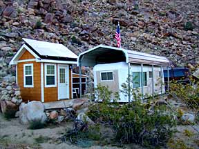
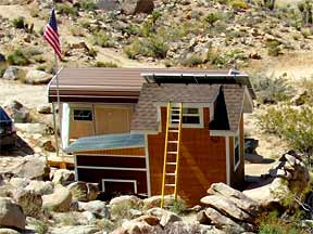
The system |
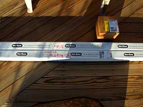
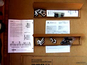
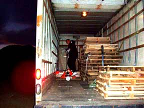
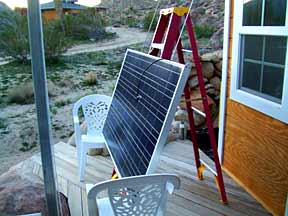
Arrival of the mounting rails and legs |
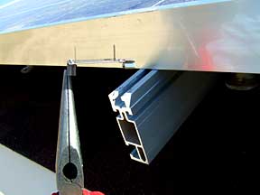
The rails, L-feet and wrong G-clamps |
|
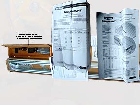
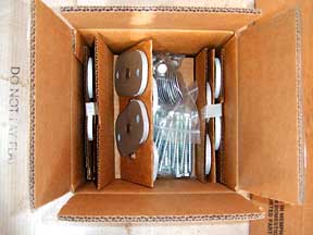
Plates, lags, standoff washers, bolts |
Standoff legs. Grounding clips. |
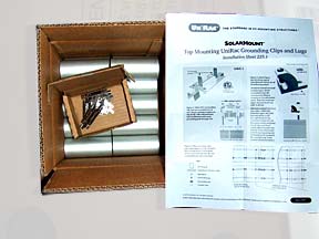
The correct F-clamps, shipped overnight |
Though solar panel arrangements on most roofs seem to be vertical, that is in a "portrait" layout, I chose the horizontal "landscape" layout simply because the shape of my roof dictated that selection. UniRac refers to them as "low-profile mode" and "high-profile mode". The selection determines in what direction the rails will be laid. In my case where the panels were to be horizontally 2 across and 2 up, the 4 rails were laid vertically in line with 4 rafters (high-profile mode) rather then across of them.
I had chosen the Sharp 216 watt panels because they were the most powerful panels that I could find that would fit on my 10' x 6' roof. These panels add up to 10'10" x 6'6", a 5" overhang at each side and 6" at the top (choosing to have the bottoms even). I could probably have safely extended another 2 feet or more at the top and at the bottom. It would just mean ordering rails of the desired length plus 6" for 2 end clamps, though it could also mean ordering splice bars to tie rails together. A 1" space for the center clamp was included into the above 6'6" height. There is no space needed between the panels side by side. I could probably have also managed an additional 6" overhang on the left and on the right.
It required finding the exact center of 8 positions, 2 on each rafter, where the legs would be attached. At each position 2 holes were drilled and lag bolts inserted and tightened - very tight; we don't want high winds pulling them out. If they are not in the exact center, the wood will be more likely to crack especially as it dries over time in the desert air. Of course the predrilling reduces that possibility.
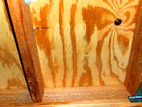
It was easy finding one center since I could get to an exposed rafter below and drive a screw up beside it, then marking the hole from above 3/4" right of the screw. BTW, that screw was driven just enough to dimple the top shingle but not enough to penetrate it - no sense creating any more potential leaks then necessary. In a perfect world finding the other 7 would be easy; just measure across allowing for a 16" separation between rafters. However, given the nature of new wood these days they will be warped to some degree; not exactly 16" apart. It would also be nice if I could just drive a screw up from below for each position but my rafters and the cross ties below them are loaded with scrap wood and other stuff. So I carefully measured inside with a 6' ruler to locate those other centers, marking them with chalk on top as I found them. As far as I can tell I was right on with each position. Checking with a flashlight later on, there were no bulges in the rafter sides where the lags had been driven through. In the end, that scrap wood had to go anyhow so that I could run wiring across to a new lamp and new outlet.
|
|
A screw marks the rafter's edge |
Finding 8 rafter centers for 8 rail feet |
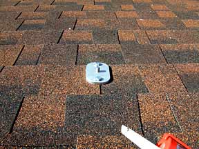
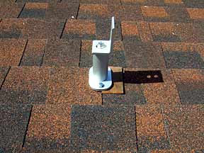
After each hole was drilled through the shingle, plywood and rafter, a dollop of silcone sealant was squeezed into the hole. Then the aluminum mounting plate was placed over the holes and a lag screw driven into each. My shingles are not the usual design; they are multi-layered so that the 5 or 6" raised flaps alternate with a 5 or 6" lower stretch between. That means that any mounting plate that laid across an edge had to be shimmed to keep it from tilting to the lower side. BTW, the 8 plates do not have to be perfectly aligned; finding exact centers is more important. But if they are not aligned then the rails will not be perfectly parallel and may look a little odd. That's a judgement call. I went for good centers.
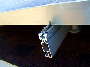
Each plate includes a bolt protruding from the center. A 4" reinforced cylindrical aluminum standoff is then loosely tightened over the bolt. For each standoff there is a slightly domed rubber backed washer and a bolt. There are also 8 L shaped feet that came with the rails. On top of each standoff goes the washer with the dome up, the L-foot, and the bolt. When the bolt is tightened the dome flattens and the standoff tightens. This leaves a side of the L ready to meet the rail just as its neighbor will further up the rafter. The rail is attached by fitting another bolt into the end of a slot that runs the length of the rail and then sliding it along the slot until it meets a hole in the L-foot where a nut is attached and tightened. Then the bolt on top of the standoff gets tightened.
I could have excluded the standoffs, attaching the washers and L-feet directly to the plates, but it can get up to 120 degrees here so the 4" standoffs allow ventillation. The L-feet also allow another 1" in height if needed depending on the hole you choose to use.
|
|
The mounting plate |
A shimmed mounting plate, leg and L-foot |
8 legs and L-feet |
|
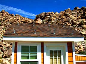
The PV mounting rails ready to go |
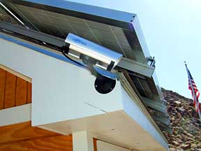
The next step is to add grounding lugs and wire across the rails. If you have not read that page then you might want to
do that now.
|
|
Delivery of the PV modules |
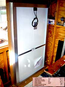
PV module front |
PV module back, with specs |
|
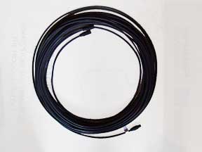
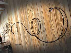
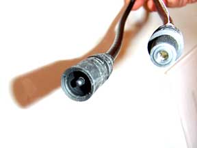
This MC3 PV cable will carry the power |
It will be cut in half to make 4 cables |
The MC3 PV cable connectors |
The 4 PV modules are arranged as 2 pair. Each panel was designed to produce approximately 24 volts. I and Aaron Cabral, the Affordable Solar sales rep, decided to make this a 48 volt system, meaning the panels will have to output 48 volts, just as the
charge controller and the
inverter will expect to receive 48 volts. Likewise the
battery bank will be cabled to receive and output 48 volts.
2013 (6 years later): 4 panels were not enough. The batteries must get a full charge at least twice a week, or they will die.
They died.
Am now adding 4 more panels on a ground mount behind these panels.
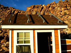
Two 24 volt panels are plugged into each other so that they will produce 48 volts. Likewise the other pair. I paired them vertically so that the cables will end up about the same length. Two "MC-3" cables are run from each pair, a total of 4 cables down the rear roof and through the wall to DC breakers in the
Combiner box. Two 50' MC-3 cables were included in the order. Those I cut in half to get 4 cables. The 4 connectors go to the panels and the 4 cut ends go to the box.
|
|
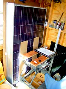
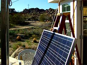
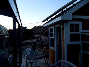
Panel 1 is up and the bottom edge is clamped |
Preparing to lift the second panel |
The tops and bottoms of both are clamped |
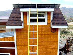
Getting the panels up was another matter. It is something that I was concerned about months beforehand and up until the 4th panel was up on its rails. They make the things to take some serious abuse, warranteed for 25 years; they might even survive a fall. However I made sure there were no objects like circular saws or whatever in the potential fall area.
The smart thing to do first would have been to get help, preferably somebody strong and over 6' with his own sturdy stepladder and rubber gloves to get a good grip - not leather gloves. I do mean stepladder; 6' or 8', no taller. The last thing you need is the top of a ladder getting in your way during the critical balancing act at the top. That is the point where you are still holding it straight up in the air, preparing to lay it gently down on the rails, without it flipping backwards and/or you falling backwards. A breeze coming the wrong way at that point would be devastating.
Another smart move would have been to rent or build a 6' scaffolding with a plywood top so that a panel could be easily lifted up and laid down on top with my feet solidly on the ground (well, deck).
|
|
Preparing to lift the third panel |
Preparing to lift the fourth panel |
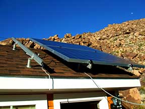
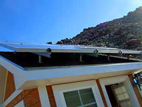
All 4 panels are up and clamped down |
Here is what I did: I set the stepladder in place, centered below the rails and out beyond the roof's edge, with its legs blocked to keep it from sliding forward. I then leaned the panel up against the ladder. I inserted the ends of two strong 1/4" nylon ropes through holes in the frame and triple knotted the ends to keep them from pulling out when stressed.
The legs of the rails are very sturdy with a good solid grip on the roof. I ran the other ends of the ropes up between the legs, around the top legs and back down outside of the legs and to a sturdy steel carport post that happened to be handy. If I did not have that post or a solid tree then I would have backed my car up and tied the ends around the window frame of a door. Again, the ropes from the panels going up have to be inside of the ropes coming down. That way as I climb and the ropes slacken, the outside ropes will fall away. If the opposite, then they would snag around each other and the rail ends, complicating matters during the balancing act. Up inside - down outside.
The idea is for the ropes to break the fall of the panel if I loose it. To make sure this happens before the panel can hit the deck I set the ends of the panel on plastic chairs when I leaned it against the ladder. Then I pulled and tied the ropes securely to the post. An assistant could have lifted it even higher against the ladder as I pulled from the other end and tied them down. That way it becomes easier to get your footing on the ladder as you grip the bottom of the panel and begin to lift.
The kit comes with 4 short "safety bolts" and nuts, with no instructions as to what they are for. I think I know. I had them in my pocket along with a wrench. After I laid the lower panel down on the rails I immediately tightened a bolt onto the bottom end of each rail. This kept the panel from sliding off as I went to work on the F-clamps (and grounding clips). I could have attached the bolts before bringing the panel up but I was concerned that they might damage the panel as I worked it up and over the rail ends. Of course they could have been there to catch the panel frame if I had slipped. The plastic backing on the panel is solid so it probably would not have damaged easily. Now I think I am in favor of the latter.
|
|
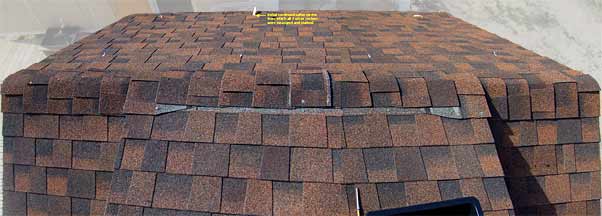
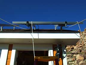
From above (merge of 3 shots) |
The panels work! |
From the rear |
|
|
|
|
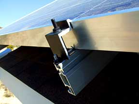
Inserting a grounding clip under the safety bolt, F-clamp and PV module |
|
I forgot the grounding clips. Every time I attached an end clamp or a center clamp I should have snapped a grounding clip into the rail's slot first. It has sharp little steel points that penetrate the aluminum surface of the rail and that of the panel frame as the clamp is tightened on top of it. This creates an excellent ground at 4 points on each panel so if lightning strikes it will have somewhere to go. Of course the previously attached copper ground lugs and wire will take it to ground. I redid the bottom 4 and one day I'll redo the top 4 and possibly I'll be able to manage the center 4. However, I know that I tightened all clamps enough to make them break the surface film so - I should be okay.
In the above photos you can see that I bent the forward end of the clip down so that it would fit snugly under the safety bolt and the adjacent end clamp.
Manufacturer's specs: Unirac (scroll down to 'SolarMount')
Manufacturer's specs: Sharp (select '216W Module Spec sheet')
|